
Working with LUTs
ART has inherited from RawTherapee the support for creative 3D LUTs in the form of Hald CLUTS, available in the Film Simulation tool. Starting from version 1.16, however, the support for LUTs has been significantly enhanced.
In particular, now ART supports two new kinds of LUTs which can be used to encode various powerful and flexible pixel-level operations:
-
ACES CLF LUTs, thanks to the use of OpenColorIO v2 (OCIO for short);
-
Scripts written in the Color Transformation Language (CTL), thanks to the use of the ACES CTL interpreter (since version 1.21).
Both kinds of LUTs must be enabled at compile time, by setting respectively ENABLE_OCIO and ENABLE_CTL to True in CMake.
When available, they can be used in both the “Film Simulation” and in the the “Color/Tone Corrections” modules.
Contents:
CLF LUTs
Despite the name, CLF LUTs are not simply look-up tables, but can encode a sequence of different pixel-level operations, including matrix multiplications, ASC CDL operations, and per-channel transfer functions. What this means is that they are well suited to be applied in a scene-referred workflow, e.g. to implement “look transforms” or also “output transforms” (i.e. tone mapping operations from scene to display/output). For example, now it is possible to apply ACES output transforms directly in ART, or even color grade pictures using look+output LUTs developed for high-end professional cinema cameras.
The only thing needed is to convert such LUTs to CLF and combine them with the appropriate color space conversions to/from ACES 2065-1 (which is the color space used by ART to apply CLF LUTs), all of which can be done with OCIO tools and a little bit of scripting.
Generating ART-compatible CLF LUTs
The OCIO distribution comes with ociomakeclf, a command-line tool to convert many LUT formats to CLF. Conveniently, ociomakeclf can also perform color space conversions from the space required by the LUT to ACES 2065-1, which is what ART assumes, via the --csc parameter.
For many “creative-type” LUTs, which do not change the color space of the input image, invoking ociomakeclf with the appropriate value for --csc is all that is needed.
For example, converting one of the ARRI Look LUTs in LogC4 space to CLF in ACES 2065-1 can be done by using --csc ARRI_LOGC4, whereas for RED Creative LUTs, instead, --csc RED_LOG3G10-RWG should be used.
The process is a bit more involved for LUTs that also perform color space conversions of their inputs, such as the LUTs used to implement output transforms in various scene-referred pipelines typically used in video editing such as ACES. In this case, the steps needed are as follows:
- Generate a CLF LUT for converting from ACES 2065-1 to the input format expected by the LUT;
- Convert the LUT to CLF via
ociomakeclf, but without any color space conversion; - Generate a CLF LUT for converting from the output format produced by the LUT;
- Combine the three LUTs above into a single one.
For example, the current output transform candidates for ACESv2 take as input an image encoded in ACEScct. Therefore, in step 1. we need to convert from linear ACES AP0 (i.e. ACES 2065-1) to ACEScct, which can be done with the following CLF LUT (let’s call it ACES-2065-1_to_ACEScct.clf):
<?xml version="1.0" encoding="UTF-8"?>
<ProcessList compCLFversion="3" id="1">
  <!-- convert from linear AP0 to linear AP1 -->
  <Matrix inBitDepth="32f" outBitDepth="32f" >
    <Array dim="3 3">
       1.4517959  -0.23689421 -0.21493762
       -0.07658145  1.17624678 -0.09967593
       0.00831917 -0.006041    0.99810067
    </Array>
  </Matrix>
  <!-- convert from linear AP1 to ACEScct -->
  <Log inBitDepth="32f" outBitDepth="32f" style="cameraLinToLog">
    <LogParams base="2" linSideSlope="1" linSideOffset="0" logSideSlope="0.0570776255707763" logSideOffset="0.554794520547945" linSideBreak="0.0078125" />
  </Log>
</ProcessList>
For step 3, assuming we want to use the “Rec.709” version of the output transforms (which is suitable for a standard SDR display), we can use the following CLF to convert from Rec.709 with a 2.4 gamma to ACES 2065-1 (let’s call it Rec709_to_ACES-2065-1.clf):
<?xml version="1.0" encoding="UTF-8"?>
<ProcessList compCLFversion="3" id="3">
    <Exponent inBitDepth="32f" outBitDepth="32f" style="basicFwd">
      <!-- rec1886 EOTF -->
      <ExponentParams exponent="2.4"/>
    </Exponent>
    <Matrix inBitDepth="32f" outBitDepth="32f" >
      <!-- Linear Rec.709 to ACES AP0-->
      <Array dim="3 3">
        0.43392843 0.3762503  0.18982151
        0.088802   0.81526168 0.09593625
        0.01775005 0.10944762 0.87280228
      </Array>
    </Matrix>
</ProcessList>
Finally, for step 4, we can use this simple Python script to obtain our final result (RESULT.clf):
$ python combine_clf_luts.py ACES-2065-1_to_ACEScct.clf LUT.clf Rec709_to_ACES-2065-1.clf -o RESULT.clf
If you want to save space, you can also compress RESULT.clf using gzip, and then rename the file to RESULT.clfz:
$ gzip RESULT.clf && mv RESULT.clf.gz RESULT.clfz
Alternatively, you can also pass the -c flag to combine_clf_luts.py to generate a compressed LUT directly.
Note though that supporting gzip compression is an ART extension, so the compressed LUTs will probably not work with other OCIO-based apps.
Generating a 3dLUT from an ART profile
The make_3dlut.py user command (to be placed in the usercommands folder of the ART configuration, together with its companion art_usercommand.py and the make_3dlut.txt entry that makes it available in the file browser) bakes the colour and tone processing of an image’s .arp sidecar into a CLF 3dLUT, which can then be used in the Film Simulation tool (or in other OCIO-based applications) on other images.
It is written in Python and does not need a POSIX shell, so it also works on Windows.
It requires Python 3 with the numpy and tifffile packages, and exiftool in the PATH.
When run from ART, a file dialog asks where to save the LUT (use the .clfz extension to get a gzip-compressed LUT), and a dialog shows the progress. It can also be run from a terminal:
$ python make_3dlut.py [-o OUT.clf] [-s small|medium|large|huge] [-c rec2020|rec709] [-z] [--no-gui] IMAGE
where IMAGE is either the image (its sidecar IMAGE.arp is used) or the .arp file itself; if there is no sidecar, the default processing parameters are used.
-s sets the size of the 3dLUT grid (16, 36, 64, the default, or 121 points per side), -c the colour space in which the LUT is generated (Rec.2020 by default), and -z compresses the output. With --no-gui no dialogs are used and -o is required.
Internally, the command applies the profile to an identity grid encoded as a 32-bit TIFF image with ART-cli, and wraps the result in a CLF file with the needed colour space conversions to/from ACES 2065-1.
Caveat: spatial effects are disabled.
A 3dLUT can only map each pixel colour to another colour independently of its neighbours, so all the tools that depend on the image content around each pixel are turned off when generating the LUT: for example sharpening, denoising, local contrast, texture boost, dehaze, grain, smoothing and the spatial guides and masks of the Color/Tone Correction tool, as well as white balance, crop, rotation, lens and geometry corrections and resizing.
As a consequence, applying the generated LUT to an image can give a result that differs, even noticeably, from applying the original .arp profile in ART, if the profile relies on any of these tools.
The LUT is also an approximation sampled on a finite grid, so very small differences are to be expected even for profiles made only of pixel-level operations; larger sizes reduce them.
Useful tools
Here are links to some useful tools for working with CLF LUTs.
CTL scripts
CTL (the Color Transformation Language) is a scripting language designed to create custom pixel-level image transformation operations. LUTs expressed as CTL scripts are even more powerful and flexible than CLF LUTs, allowing to define complex image manipulation operations as programs in a language similar to C or C++.
Importantly, CTL scripts in ART can be parametric:
by using specially-formatted comments in the script, users can declare that some arguments of the main function of the script are parameters
that can be changed directly from the ART GUI
(and whose values are stored in .arp sidecar files).
This provides a simple but powerful way of extending ART with user-written filters.
Writing ART-compatible CTL scripts
In order to be usable within ART, a CTL script must define a function called ART_main,
which is the entry point called by ART.
The function should take 3 varying input arguments of type float
and 3 corresponding varying output arguments, again of type float.
Such arguments correspond to the red, green and blue components of each pixel of the image being processed.
Specifically, the function will be called for every pixel of the input image,
which is in RGB format and normalized so that the SDR tonal range corresponds
to the [0, 1] interval (though the data might exceed such range both in
input and in output).
By default, the RGB values are encoded in the ACES 2065-1 color space,
but this can be overridden by inserting in the scritp an ART color space tag in the following form:
// @ART-colorspace: "<colorspace>"
where <colorspace> can be ACES2065-1 (default), ACEScg, Rec2020, Rec709, ProPhoto, or AdobeRGB.
Additionally, ART_main might take an arbitrary number of other uniform arguments of type int, float, bool, or arrays of float,
which will be interpreted as parameters for the script.
Each such parameter must come with an
associated ART parameter definition in the CTL script. ART parameter
definitions are special comment lines of the following form:
// @ART-param: <param-def>
where <param-def> is an array in JSON format, whose content depends on the
parameter type. The array must be at least of size 2; the first element is
a string containing the name of the parameter (which must mach the name
used in ART_main), and the second element is its GUI label. The rest of the
array has the following structure:
-
for
boolparameters, the 3rd optional element specifies the default value; the optional 4th and 5th elements instead are respectively:- a “group name” for the GUI: if set, this will cause the control to appear under a collapsible panel with the given name in the GUI;
- a tooltip string for the GUI: if set, the given string in Pango markup format is used as a tooltip.
-
for
floatparameters, the array size must be at least 4 and at most 8. The 3rd and 4th elements are the minimum and maximum values for the GUI slider. The optional 5th element is the default value, the optional 6th element the precision to use in the GUI (e.g. 0.01 will use 2 decimal digits in the GUI), and the optional last two elements are the GUI group name and tooltip; -
for
intparameters, the array size must be at least 3 and at most 7. If the 3rd parameter is an array of strings, it is interpreted as a list of options in a choice menu, with values corresponding to their index in the array (i.e. the 1st option will give a value of 0, the 2nd a value of 1, etc.). In this case, the array can contain at most 3 other elements, which are respectively the default value and the optional GUI group name and tooltip.
If the 3rd parameter is not an array of strings, then the array size must be at least 4, with the 3rd and 4th elements corresponding to the minimum and maximum values for the GUI slider. The optional 5th element is the default value, and the optional last two elements are the GUI group name and tooltip. -
arrays of
floatare used to represent curves as 1D LUTs. Both curve types supported by ART (i.e. “diagonal” and “flat”) are available, depending on the parameter definition. The array size of the parameter definition must be at least 2 and at most 8. The 3rd parameter indicates the curve type: 0 for diagonal, 1 for flat, and 2 for periodic flat (e.g. like a hue curve in ART). If not given, it defaults to 0. The 4th parameter, if given, specifies the default value for the curve. This can either be 0 (i.e. an identity curve), or an array of floats defining the type of curve and its control points, in the format used by .rtc curve files. The 5th and 6th parameters can be used to define the gradients appearing at the bottom and left of the curves in the GUI. Finally, as for other parameter types, the last two optional elements are the GUI group name and tooltip string.
If default values are not given in the ART parameter definition, they are
taken from the definition of the ART_main function. If no default is given,
zero is used.
Here is an example of parameter definitions for each of the supported types.
For param_float, besides the required minimum and maximum values, we also specify the default and the GUI precision;
for param_int, only the required elements are provided;
for param_bool, a default value of true is given;
finally, for param_choice, all the possible elements are provided.
// @ART-param: ["param_float", "A float slider", -1.0, 1.0, 0.5, 0.1]
// @ART-param: ["param_int", "An int slider", -10, 10]
// @ART-param: ["param_bool", "A checkbox", true]
// @ART-param: ["param_choice", "A combo box", ["Option A", "Option B"], 1, "Choice group", "Tooltip <b>using markup</b>!"]

void ART_main(varying float r, varying float g, varying float b,
              output varying float r_out, output varying float g_out, output varying float b_out,
              float param_float, int param_int, bool param_bool, int param_choice)
{
   // ...
}
Using the @ART-lut tag it is possible to specify whether the CTL script should be applied to every pixel of the input image, or whether it should be used to precompute a 3dLUT that is then applied to the image.
The use of @ART-lut can significantly improve performance, but it might cause
artifacts for scripts that compute functions that are hard to approximate with
a look-up table. By default, if no tag is present, ART will apply the CTL
script to each pixel of the image on export, and it will use intermediate
3dLUTs of suitable size during the editing preview (this behaviour can be changed by setting the related flag in “Preferences -> Performance”).
The format for the parameter is the following:
// @ART-lut: <lut-dim>
where <lut-dim> is an integer specifying the dimension of the intermediate
3dLUT. The special value -1 means that 3dLUTs are never used for this
script, neither on export nor for previews.
Pipettes for curves
Curves defined by a CTL script can have a “pipette”, i.e. the button that, like
for the built-in curves (e.g. the tone curve or the RGB curves), lets you hover
over the image to see where the pixel under the cursor falls on the curve, and
Ctrl+click to add a point to the curve at that position. Since ART cannot know
what the input of a curve is, a script that wants to support this must say so
with the @ART-pipette tag, and provide a second entry point,
ART_fill_pipette, that computes the position in the curve for each pixel.
The format of the tag is the following:
// @ART-pipette: [<curve-name>, <curve-name>, ...]
where each <curve-name> is the name of a curve parameter of ART_main (see
above). The position of a curve in this list is its curve id. Only the curves
in the list get a pipette button. The tag can appear anywhere in the script. It
is an error to name a parameter that does not exist or that is not a curve.
The entry point has the following signature:
void ART_fill_pipette(varying float r, varying float g, varying float b,
                      output varying float r_out, output varying float g_out, output varying float b_out,
                      int curve_id)
The r, g, b input values are exactly those that ART_main would receive
for the same pixel (in particular, they are converted to the colorspace given
by @ART-colorspace, if any). curve_id is a uniform int, which tells which
curve (according to the order of the @ART-pipette list) the pipette is for.
The function must write in the output variables the position on the x axis of
that curve that corresponds to the pixel, in the range [0, 1]. As for the
built-in curves, the three outputs are the values for the red, green and blue
channels; a channel that is not meaningful for the curve can be set to -1 to
be ignored. Most curves will simply set all three outputs to the same value.
Like ART_main, ART_fill_pipette can have additional uniform parameters,
declared after curve_id. They are matched by name and type with the
parameters of ART_main, and receive the same values. This is useful if the
position in the curve depends on other parameters of the script. Parameters
not present (or with a different type) in ART_main are not set and keep their
default value.
If @ART-pipette is used but ART_fill_pipette is missing or has a wrong
signature, the script still works but no pipettes are available (a message is
printed in verbose mode).
For example, here is a script with a curve acting on the luminance of the pixels, and its pipette:
// @ART-param: ["lcurve", "Luminance curve", 0, 0]
// @ART-pipette: ["lcurve"]

void ART_main(varying float r, varying float g, varying float b,
              output varying float r_out, output varying float g_out, output varying float b_out,
              float lcurve[256])
{
    // ... apply the curve to the luminance
}

void ART_fill_pipette(varying float r, varying float g, varying float b,
                      output varying float r_out, output varying float g_out, output varying float b_out,
                      int curve_id)
{
    // the input of the curve is the luminance of the pixel
    float Y = 0.2126 * r + 0.7152 * g + 0.0722 * b;
    r_out = Y;
    g_out = Y;
    b_out = Y;
}
Pipettes are available both in the Film Simulation tool and in the LUT mode of the Color Correction tool (where each region has its own pipettes).
Spatial guides
By default ART_main is called on each pixel independently, so a script cannot
know anything about the neighbourhood of the pixel it is processing. A script
can however ask ART for one or more guides: additional input channels carrying
spatial information, which makes it possible to implement local (e.g. detail-preserving)
operations such as local tone mapping, or to make a colour operation act coherently
on neighbouring pixels instead of amplifying the noise of each of them.
To use them, add up to three varying input arguments of type float, right after
b and before the output arguments:
// @ART-guides: ["Y"]
void ART_main(varying float r, varying float g, varying float b,
              varying float guide,
              output varying float r_out, output varying float g_out, output varying float b_out,
              float expcomp)
{
    // ...
}
The guides are detected by position: the varying arguments following r, g and b are guides
(and they must be floats), while the first output argument starts the outputs.
The @ART-guides tag says how each guide is computed. Its value is a list of names in
JSON format, one for each guide, in the same order as the arguments of ART_main.
The available guides are:
| name | guide |
|---|---|
"Y" |
The luminance of the input image, smoothed with an edge-aware filter (the same as the one used by the Tone Equalizer tool, with regularization 4). It is a linear luminance, normalized as in the Tone Equalizer, so that 0.18 corresponds to middle grey. |
"C" |
A chroma-like quantity: the smoothed (edge-aware) chroma cz of the pixels in the JzAzBz colour space, multiplied by 15 so that it is 0 for neutral colours and about 1 for strongly saturated ones. |
"H" |
A hue-like quantity: the smoothed (edge-aware) hue angle hz of the pixels in the JzAzBz colour space, in radians, in the range (-π, π]. Colourful neighbours count more than grey ones, and the average is taken in a way that works across the wrap point of the angle. Note that it is an angle: differences between hues must be wrapped by the script. |
The same guide cannot be listed twice. If the tag is missing, a script with exactly one guide gets the "Y" guide;
a script with more than one guide must use the tag. The number of names in the tag must match the number of guides taken by ART_main.
For example, a script using all the guides looks like this:
// @ART-guides: ["Y", "C", "H"]
void ART_main(varying float r, varying float g, varying float b,
              varying float guide_y, varying float guide_c, varying float guide_h,
              output varying float r_out, output varying float g_out, output varying float b_out)
{
    // ...
}
A few things to keep in mind:
- the guides are not expressed in the colour space of the script
(see
@ART-colorspace), but in the working profile of ART; - they are computed once from the input of the tool, before any of its regions is applied (in the Color/Tone Correction tool); only the guides that are needed are computed.
A typical use of the "Y" guide is to compute a gain from the guide and apply it to r, g, b:
since the guide is smooth, the gain varies slowly across the image, and the
local contrast of the pixel is preserved. Computing the gain from the luminance
of the pixel itself, instead, behaves like a tone curve, which also compresses
the local contrast.
For example, here is a simple script that lifts the shadows depending on the local brightness:
// @ART-param: ["amount", "Shadows lift (Ev)", 0.0, 4.0, 1.0, 0.1]

void ART_main(varying float r, varying float g, varying float b,
              varying float guide,
              output varying float r_out, output varying float g_out, output varying float b_out,
              float amount)
{
    // the darker the neighbourhood, the stronger the gain
    const float t = clamp(guide / 0.18, 0.0, 1.0);
    const float gain = pow(2, amount * (1.0 - t));
    r_out = r * gain;
    g_out = g * gain;
    b_out = b * gain;
}
The "C" and "H" guides are useful for colour operations that move the hue or the chroma of the pixels
(for example to pull the colours toward a palette): computing the amount of the change from the smoothed hue and chroma,
instead of from the values of each pixel, avoids that noisy pixels get shifted in different directions, which would produce visible artifacts.
The "C" guide is scaled so that it is 0 for neutral colours, around 0.1–0.3 for typical skin tones and other moderately coloured areas,
and close to 1 for strongly saturated colours (it can go somewhat above 1 for very saturated colours, especially with a wide-gamut working profile).
Weights such as c / (c + k), used to protect neutral areas, work well with k of the order of 0.01–0.05.
Note that this scaling is applied on top of the plain JzAzBz chroma: the "C" guide is 15 times the cz of the same colour.
This matters if a script wants to compare the guide with the chroma of the pixel itself, computed from its r, g, b values
(for example with rgb2jzczhz from _artlib.ctl, which returns the unscaled cz):
either multiply that chroma by 15, or divide the guide by 15, before comparing them or mixing them in the same formula
(e.g. c_pixel * ART_GUIDE_C_SCALE / (guide_c + k)).
The factor is available as the constant ART_GUIDE_C_SCALE (currently 15.0) in _artlib.ctl,
so scripts that import "_artlib"; should use it instead of hardcoding the number. Forgetting to do so makes the guide look 15 times too large,
and a pixel in a perfectly flat area will appear much less chromatic than its own neighbourhood.
Also keep in mind that, even with the same scale, the two values are not expected to be identical:
the guide is an edge-aware average over a neighbourhood and not the value of the pixel,
it is computed in the working profile of ART (while r, g, b are in the colour space of the script, see @ART-colorspace),
and it is computed from the input of the tool, before any of its regions is applied.
Limitations:
- scripts that use guides are never converted to an intermediate 3dLUT, since
their result does not depend only on the colour of the pixel. Therefore, any
@ART-luttag is ignored (a warning is printed in verbose mode), and the script is always applied per pixel, which can be slower; - guides are available only in the tools that provide them, i.e. the Color/Tone Correction and the Film Simulation tools;
-
if
ART_maintakes guides, thenART_fill_pipette(see above) must take them too, in the same positions, i.e. afterband before the output arguments:void ART_fill_pipette(varying float r, varying float g, varying float b, varying float guide_y, varying float guide_h, output varying float r_out, output varying float g_out, output varying float b_out, int curve_id)
Presets
Finally, it is also possible to define different presets for the script by using the @ART-preset tag. The format is the following:
// @ART-preset: [<preset-name>, <gui-name>, <preset-dictionary>]
where:
-
<preset-name>is a string, defining the (unique) name for the preset; -
<gui-name>is the name as shown in the GUI; -
<preset-dictionary>is a dictionary mapping parameter names to parameter values for the preset. Note that not all parameters need to be specified in the dictionary: in that case, applying the preset will only affect the parameters that are specified, and leave the other ones unchanged.
A script can have zero or more preset lines. If present, they must
occur after the definition of parameters (with the @ART-param tag).
Continuing the example above, here are some possible preset definitions:
// @ART-preset: ["full", "A full preset", {"param_float" : 0.4, "param_int" : -3, "param_bool" : false, "param_choice" : 1}]
// @ART-preset: ["partial", "A partial preset", {"param_float" : 0.4, "param_int" : -3}]
Example
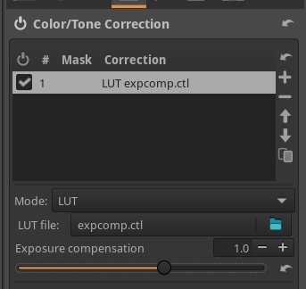
Here is a simple ART-compatible CTL script to perform exposure compensation. The script takes one parameter that gives the Ev value of the exposure correction to apply. The CTL code looks like this:
// @ART-param: ["expcomp", "Exposure compensation", -5.0, 5.0, 0, 0.1]

void ART_main(varying float r, varying float g, varying float b,
              output varying float r_out, output varying float g_out, output varying float b_out,
              float expcomp)
{
   const float scale = pow(2, expcomp);
   r_out = r * scale;
   g_out = g * scale;
   b_out = b * scale;
}
The corresponding GUI when loaded in ART (in the “Color/Tone Correction” tool) looks like this:
More complex examples
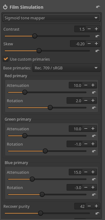
Starting from version 1.21, ART ships with a (slightly simplified) implementation of the Sigmoid tone mapper of darktable as a CTL script. This can be used as an alternative tone mapper for ART, and it is automatically available in the “Film Simulation” module (if CTL support was enabled at compile time):
A collection of other examples are available in this repository.
Making CTL scripts automatically available
CTL scripts placed in the ctlscripts subdirectory of the ART config folder
(typically $HOME/.config/ART on Linux and %LOCALAPPDATA%\ART on Windows)
are loaded automatically by ART upon startup,
and available as additional operation modes in the “Color/Tone Correction” tool.
For example, by putting our expcomp.ctl example in $HOME/.config/ART/ctlscripts, we have it as an additional mode:
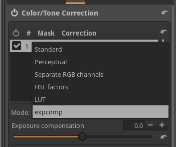
By default, the name of the file (without the .ctl extension) is used as mode name.
This can be customized by adding an ART label tag to the CTL script,
with the following format:
// @ART-label: "<toolname>"
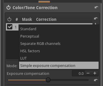
For example, by adding:
// @ART-label: "Simple exposure compensation"
to expcomp.ctl, we now get a nicer name in the GUI:
Controlling the list and order of LUTs
By default, the LUTs and CTL scripts found in the directories scanned by ART are listed sorted by name.
Since ART version 1.26.11, this can be customized by putting in a directory a text file called ARTlist.txt
(the name is matched case-insensitively, so e.g. artlist.txt works too).
If present, the file determines which LUTs are shown in the GUI, and in which order.
If no ARTlist.txt is found, the default behaviour is used.
The file contains one entry per line. Anything starting with a # and up to the end of the line is ignored,
and so are blank lines. For example:
# my favourite looks
ART_agx_film.json
warm_look.clfz     # trailing comments are fine
Entries that do not exist are skipped, as are duplicates. Only the files and directories listed are shown: anything else in the directory is hidden.
CTL scripts in the Color/Tone Correction tool
The ARTlist.txt file is looked for in the ctlscripts subdirectory of the ART config folder, and in the ctlscripts folder shipped with ART.
Each entry is the name of a file in the same directory as the ARTlist.txt file (or an absolute path).
The listed scripts are shown in the given order, before the scripts coming from directories without an ARTlist.txt (which are sorted by name as usual).
The Film Simulation tool
In the Film Simulation tool, ARTlist.txt is only looked for in the top-level directories scanned by ART
(i.e. the ones shipped with ART and the LUTs directory set in “Preferences”), and not in their subdirectories.
Entries are paths relative to the top-level directory, and can refer to files in subdirectories,
for example:
ART_agx_film.json
my_look.clf
negatives/kodak_portra.clf
negatives/fuji_400h.clf
slides/velvia.clf
negatives/ilford.clf
Files in subdirectories are shown in a separate group (submenu) named after the subdirectory.
Groups appear in the position of their first entry in the list, and the files inside each group follow the order in the list.
In the example above, the menu will show ART_agx_film, my_look, then the group negatives (with Portra, 400H and Ilford, in this order),
and finally the group slides.
An entry naming a subdirectory (e.g. slides) adds a group with all the files of that directory, sorted by name.
Nested subdirectories (e.g. a/b/file.clf) give nested groups.
ARTlist.txt files inside subdirectories are ignored.